
|
|
Area personale
Cerca in questo Blog
Menu
Ultimi commenti
Chi può scrivere sul blog
| « Adapter – Convert & Impo... |
In this guide I explain how to disassemble an HP Pavilion dv7 notebook.
To be precise, I’m taking apart an HP Pavilion dv7t-1000 notebook but you should be able to use these instructions for all models in the Pavilion dv7 line.
The guide will show how to access both memory modules and hard drives if you are upgrading the notebook, remove most internal components, access and clean the cooling fan.
Before you start, turn off the notebook and remove the HP Pavilion dv7 battery.
STEP 1.
Remove (loosen) four screws securing the hard drive and memory cover. Remove the cover.

STEP 2.
Remove four screws securing hard drives (two screws per hard drive).
Slide the hard drive 1 to the left until it’s disconnected from the motherboard. Remove the hard drive 1.
Slide the hard drive 2 to the right until it’s disconnected from the motherboard. Remove the hard drive 2.

STEP 3.
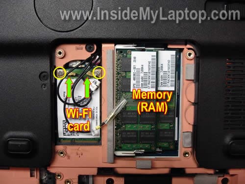
Remove both memory (RAM) modules.
Disconnect two antenna cables from the wireless card. These laptop has three antenna cables but only two are used.
One of the antenna cables connected to the main contact on the wireless card and the second one is connected to the auxiliary contact. All three antenna cables are labeled.
Remove two screws securing the wireless card. Remove the card.
STEP 4.
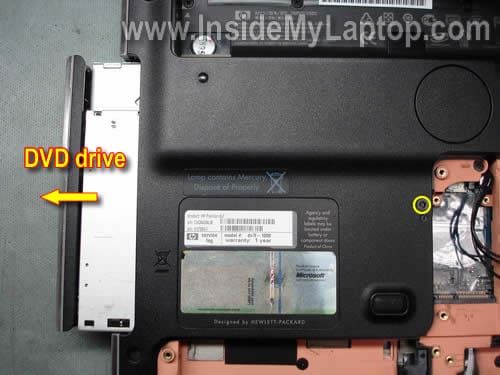
Remove one screw securing the CD/DVD drive.
Slide the CD/DVD drive to the left to disconnect it from the motherboard.
Remove the CD/DVD drive.
STEP 5.
Remove all marked screws from the bottom of the notebook.
The green circled screw secures the keyboard.

Don’t forget to remove two screws hidden in the CD/DVD drive bay.

STEP 6.
Start separating the speaker cover from the notebook base.
You can use a guitar pick as a case cracker. Insert the guitar pick between the speaker cover and case and slowly move along the side.

STEP 7.
Lift up the speaker cover. Be careful, it’s still connected to the motherboard.
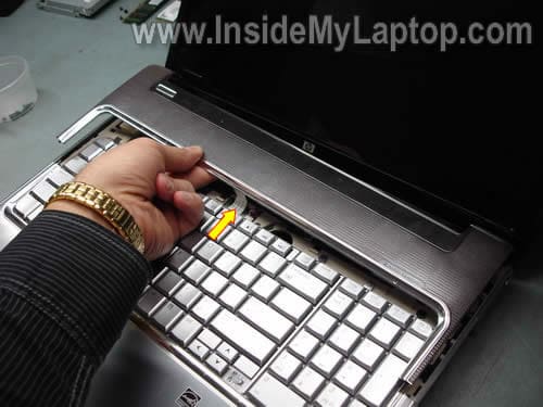
In order to remove the cable, you’ll have to unlock the connector first.
Move the brown clip about 2 millimeters in the direction shown by two arrows. The clip must stay attached to the connector base.
On the picture below the connector is shown in the unlocked position.

STEP 8.
Now you can remove the speaker cover.

STEP 9.
Remove four screw securing the keyboard.

STEP 10.
Lift up the keyboard from the base and access the cable connector underneath.

STEP 11.
Carefully unlock the keyboard cable connector.
Move the brown clip about 2 millimeters in the direction shown by two arrows. The brown clip must stay attached to the connector base.
If you damage the connector, the keyboard will not work when you assemble the notebook back together.

Well… I broke the connector. I removed thousands of laptop keyboards before but I broke this connector!
As you see, the left pin on the brown clip is missing.
No panic! I still can use this clip to lock the connector.
You’ll find more info here: Fixing damaged keyboard connector on a laptop motherboard.

STEP 12.
Pull Wi-Fi antenna cables though the opening in the cover.
Remove three screws securing the speaker assembly.
Disconnect the speaker cable (green arrow) from the motherboard.

STEP 13.
Remove the speaker assembly.

STEP 14.
Disconnect the video cable from the connector on the motherboard.
Remove six screws securing display hinges (three screws per hinge).

STEP 15.
Separate the display assembly from the notebook base.
In the next post I will explain how to take apart the display panel assembly and remove the LCD screen with inverter board.
By the way, it’s not necessary to separate the display panel assemble from the base in order to take it apart.

STEP 16.
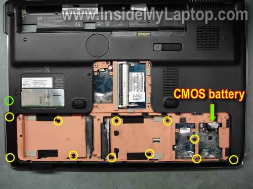
Disconnect and remove the CMOS battery.
Remove all marked screws from the bottom. The green circled screw is hidden in the CD/DVD drive bay.
STEP 17.
Remove all screws securing the top cover assembly.
Disconnect the touch pad cable from the motherboard.

STEP 18.
Start separating the top cover assemble from the notebook base.
You can use same trick with the guitar pick shown in the step 6.

STEP 19.
Remove the top cover assembly.

Here’s the back side of the top cover assembly.

STEP 20.
Disconnect the USB and audio board cables from the motherboard (green arrows).
Disconnect the cooling fan cable from the motherboard (yellow arrow).
Remove four screws securing the motherboard.

STEP 21.
Lift up the right side of the motherboard as it shown on the picture below and disconnect the DC-IN jack cable.

STEP 22.
Remove the motherboard from the notebook base.

On the opposite side of the motherboard you can access the processor (CPU) when the heat sink is removed.

By the way, the best way to find a replacement motherboard is searching by the HP part number. The part number should be located on a sticker in the memory compartment. The HP part number looks like XXXXXX-001.
Here’s the notebook base without motherboard.
The USB board, audio board, cooling fan and DC-IN jack are mounted on the base.
The DC jack attached to a harness. New jack harness for dv7 notebooks available here.

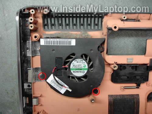
In order to remove the cooling fan, simply remove two screws securing the fan.
As you see, the cooling fan is dusty and has to be cleaned.
UPDATE:
There are only two fans listed in the service manual for HP Pavilion dv7 series notebook. They are listed on the page 27.
488885-001 for laptops equipped with AMD processor.
480481-001 for laptops equipped with Intel processors.
One of the DIY-ers had trouble searching for a new replacement fan for her AMD notebook. After the notebook was disassembled, she found that it had an Intel fan installed.
Related Batteries:
- HP PAVILION DV8 Battery
- hp pavilion dv7-1070ee Battery
- hp pavilion dv7-1110ed Battery
- hp pavilion dv7-1140eo Battery
- hp pavilion dv7-1205eg Battery
- hp pavilion dv7-1290eo Battery
- hp pavilion dv7-2002tu Battery
- hp pavilion dv7-2006tx Battery
- hp pavilion dv7-2117tx Battery
- hp pavilion dv7-2201tx Battery
- hp pavilion dv7-2206tx Battery
- hp pavilion dv7-3001xx Battery
- hp pavilion dv7-3060ca Battery
- hp pavilion dv7-3069wm Battery
- hp pavilion dv8-1009tx Battery
- 464058-161
- 464058-362
- 464059-122
- 464059-141
- 464059-142
- 464059-161
- 464059-361
- 480385-001
- 509422-001
- 534116-291
- dyna-cha-loc
- ga06047
- hstnn-db74
- hstnn-ib75
- hstnn-ob75
- hstnn-q34c
- hstnn-q35c
- hstnn-w50c
- ks525aa
|
|
https://blog.libero.it/laptopparts/trackback.php?msg=10590854
I blog che hanno inviato un Trackback a questo messaggio:
Nessun Trackback
|
|
|


Inviato da: wholesale10
il 27/10/2011 alle 02:25
Inviato da: wholesale10
il 27/10/2011 alle 02:24
Inviato da: wholesale10
il 27/10/2011 alle 02:24