Comparison of Two Parallel Technologies in 200G Optical Modules

According to data disclosed by Google, Facebook, etc., the internal traffic of these Internet giant data centers is increasing by nearly 100% every year. Currently, some Internet giants deploying 100G earlier have begun to seek higher-speed solutions, and the choice of next-generation data centers has become A topic that everyone is enthusiastic about.

The 400G Ethernet standard is preceded by the 200G Ethernet standard, which may reflect the industry’s mindset—more optimistic about 400G, or 200G is just a transition solution for 400G.

But directly from 100G to 400G is actually not very scientific.

  1. First of all, from the data center side, we need to rebuild the ultra-large-scale data center and define a new specification architecture. The requirements for rack power in the 400G era switch will be quite high, and the traditional air-cooling heat dissipation is more difficult.
  2. Furthermore, the 400G data center will use PAM4 technology, and the PAM4 technology will make the system less transparent and difficult to manage. The traditional NRZ technology together with the parallel technology can make the data center easy to manage.

In order to more flexibly adapt to the needs of the future data center and achieve a perfect transition to the 400G data center, Gigalight recently completed a low-cost data center internal parallel optical interconnection solution based on 200G NRZ transmission. This paper mainly compares 200G NRZ—Two parallel technologies in the solution, and two products as an example for simple analysis.

Fiber Parallel Solution—Is It Single- or Multi-Mode?

The traditional parallel optical module products are mainly based on optical interconnect technology of multimode fiber, and have the advantages of high bandwidth, low loss, no crosstalk and matching and electromagnetic compatibility problems. They have gradually replaced copper-based electrical interconnection products and are used in cabinets. High-speed interconnection between the boards, the connection distance is up to 300 meters under the OM3 fiber.

At the same time, in order to apply to longer-distance transmission solutions, Parallel Single-Mode (PSM) optical modules have emerged, mainly using FP lasers to transmit 2km in single-mode fiber and DFB to transmit 10km applications, which is more difficult than multi-mode interconnection technology.

Data center cabling is a very complicated problem. The choice of multimode fiber or single-mode fiber has been the subject of heated discussion in the industry. There are also choices in major data centers. For example, in the 100G era, Facebook chooses single mode, Google chooses both multimode and single mode. At the same time, BAT (Baidu, Alibaba, Tencent) chooses multimode. From the perspective of cost, multimode fiber is expensive and multimode optical module is cheap. Single mode fiber is cheap and single mode optical module is expensive. Therefore, it is easy to combine the cost of fiber and optical module to obtain the relationship between distance and cost. Taking the 100G solution as an example, the cost advantage of a multimode solution is very obvious when the fiber distance is within 100 meters.

The parallel technology route is characterized in that each pair of multimode fibers respectively carries one optical signal. At present, IEEE’s 400G SR16 standard is a 16x 25G parallel solution, which requires 16 pairs of multimode fiber. It is far more than the 12-core MPO widely used in the 100G era, which will lead to a significant increase in cost; more importantly, multimode optical modules rely on The low-cost VCSEL optical chip solution, 2020, is likely to still require more than 12-core MPO’s 8-pair multimode fiber. The 400G SR4 that the existing 12-pin MPO can accommodate seems to be in the foreseeable future.

Therefore, in 2020, if there is no open and standardized multi-mode wavelength multiplexing technology (such as SWDM technology), low-cost VCSEL 100G technology can not achieve breakthrough, 400G multi-mode fiber solution cost advantage will no longer be obvious, single-mode fiber It may become mainstream in large-scale data centers, and short- and medium-range single-mode parallel solutions will be a cost-effective alternative to multi-mode parallel solutions.

——Yang Zhihua, “Top Ten Hotspots of Data Center Network Technology in 2020”

200G PSM8 vs. 200G SR8

Based on Gigalight’s unique PSM series product line, Gigalight recently released a new product—200G QSFP-DD PSM8, a high-speed product of single-mode parallel technology.

To achieve long-distance transmission, single-mode fiber with low dispersion loss must be used. To achieve high coupling efficiency between single-mode fiber and semiconductor, it is necessary to shape the light field emitted by the semiconductor laser to maximize the incident light field and the intrinsic optical field of the fiber.

And the 200G QSFP-DD SR8 uses an 8-channel 850nm VCSEL array that complies with the 100GBASE-SR4 protocol standard. The 200G QSFP-DD SR8 is a multimode parallel product. With the traditional VCSEL advantage platform, Gigalight uses a simple, efficient and reliable fiber coupling process technology to add a 45° prism between the laser and the fiber. The special material treatment of the fiber surface increases the coupling efficiency of the fiber to over 80%.

The two products are similar in that they belong to the optical modules in the 200G data center solution, and all use the QSFP-DD package, which can use the 16-core MTP.

The advantage of QSFP-DD is that the 1U panel can achieve a density of 36x 200G/400G, and it is forward- and backward compatible with QSFP, and is compatible with existing QSFP28 optical modules and AOC/DAC.

The main difference is that the 200G QSFP-DD PSM8 adopts an 8-way 1310nm single-mode fiber parallel solution with a transmission distance of up to 10km. The 200G QSFP-DD SR8 adopts a multi-mode fiber parallel solution and can travel over the OM4 fiber link. Up to 100m.

Summary

The multi-mode parallel solution is the core of the current data center development, and the transmission distance between the switch and the core switch is just within the scope of the multi-mode fiber.

Corning has introduced OM5 fiber in the past few years, but it has not caused the expected market reaction. The SWDM short-range wavelength division multiplexing scheme is only promoted by a few manufacturers—it is indeed lacking in the market.

In the near future, if a general enterprise data center wants to continue to use standard-certified solutions and reduce the cost of optical components, you can choose multi-mode parallel optics—after all, SMBs do not need as large a capacity as 400G.

However, if it is in the construction and deployment process of a very large-scale data center, especially considering the scalability of the system and the flexibility of the system, we should probably consider the single-mode parallel solution.

In the eyes of some people of insight, the single-mode parallel solution increases the number of fiber cores, but overall reduces the maintenance complexity, is easier to manage, and is easier to upgrade from 100G to 400G later. Without increasing fiber resources, the current 100G CWDM4 based on wavelength division multiplexing can only evolve to 200G FR4, and 100G PSM4 can be upgraded to 400G DR4).

——Li Mofei, “Review of Data Center: Cost Technology is Concise and Reconfigurable”

In general, the technology roadmap for major switch and transceiver vendors shows a very clear and simple migration path for customers deploying parallel optics. So when optics are available and migrated from 100G to 200G or 400G, their fiber infrastructure still exists and no upgrades are required.

Reliability, product life and maintenance costs are all interrelated. The parallel single-mode solution represented by 200G QSFP-DD PSM8 in total cost should be the cabling guide for large-scale data centers in the future.

Originally article: Comparison of Two Parallel Technologies in 200G Optical Modules

Le tecnologie dei ricetrasmettitori ottici di prossima generazione – PAM4 e 64QAM

Tecnologie PAM4 e 64QAM

Il passaggio ai servizi cloud e alle reti virtualizzate ha messo il data center nel mezzo del nostro mondo e ha significato che la connettività all’interno dei data center e tra i data center ha un enorme impatto sulla fornitura di servizi aziendali e personali. I data center Hyperscale vengono installati in tutto il mondo e questi hanno tutti bisogno di essere connessi. Per soddisfare questa domanda, i fornitori di ricetrasmettitori ottici stanno offrendo nuove soluzioni basate su PAM4 e 64QAM, fornendo una modulazione coerente che ridurrà il costo della connettività e aumenterà la larghezza di banda di ciascuna connessione.

Le connessioni a molti server sono già 25G e i collegamenti tra switch in data center di grandi dimensioni sono già 100G. L’introduzione dei transceiver SFP28 e QSFP28 che integrano le nuove tecnologie e sono state costruite utilizzando tecniche di produzione efficienti hanno ridotto il costo di queste connessioni e consentito una crescita massiccia nel mercato. La fase successiva è l’introduzione di soluzioni a singola lambda 100G e ricetrasmettitori a basso costo 400G per i collegamenti tra switch. I dispositivi PHY necessari per questo passaggio successivo sono già disponibili, i dispositivi switch da 12,8T sono in produzione e i primi ricetrasmettitori ottici QSFP-DD e OSFP 400G sono di campionamento.

QSFP-DD

L’ascesa dell’operatore di data center hyperscale ha cambiato radicalmente il mercato. Il passaggio a 25G e 100G da 10G e 40G è avvenuto molto rapidamente. L’ampiezza e il numero di data center installati o aggiornati significa che le nuove tecnologie possono essere spedite in volume non appena il prezzo è giusto, i componenti sono stati qualificati e le linee di produzione sono operative. Ora stiamo vedendo i primi dispositivi 400G PHY e ricetrasmettitori ottici per la disponibilità di data center e le aziende stanno gareggiando per la posizione di mercato in attesa che i principali operatori hyperscale si impegnino a implementazioni di grandi dimensioni.

Molte di quelle aziende che hanno beneficiato di 25G e 100G stanno investendo i propri investimenti in soluzioni Lambda PAM4 100G e 400G per il data center . Ciò ha richiesto nuovi dispositivi PAM4 PHY progettati per soddisfare i limiti di potenza dei transceiver OSGP e QSFP-DD 400G. Alcune aziende hanno anche investito in PHG 50G e 200G PAM4, consentendo un aggiornamento economico da 25G e 100G. Si prevede che i ricetrasmettitori 50G SFP56 e 200G QSFP56 siano soluzioni provvisorie, ma non è chiaro quanto sia diffuso il loro uso o per quanto tempo. 40G è stata una soluzione provvisoria che è durata per molti anni.

La tecnologia coerente, originariamente sviluppata per reti a lungo raggio da 100G, è ora ampiamente utilizzata per le connessioni a lungo raggio, comprese le reti sottomarine, metropolitane e Data Center Interconnect (DCI) tra i data center. Il mercato per DCI è cresciuto rapidamente, con molti fornitori di sistemi che offrono soluzioni con una copertura da 80 a 500 km. Per le applicazioni a lungo raggio e metropolitane, numerosi produttori leader di apparecchiature continuano a utilizzare progetti di DSP (Digital Signal Processor) coerenti all’interno dell’azienda. La soluzione coerente DSP è ora disponibile per i fornitori di ricetrasmettitori ottici come Gigalight che invierà transceiver 400Gbasato su questo disegno. Gli ultimi ASIC DSP stanno abilitando le soluzioni 600G (64Gbaud 64QAM) e i transceiver CFP2-DCO. Il passo successivo è l’introduzione dei DSP 7nm che consentiranno l’utilizzo di transceiver ZR 400G a costi contenuti per collegamenti 400G fino a 100 km a partire dal 2020.

Questo continua ad essere un mercato in divenire. Lumentum ha completato l’acquisizione di Oclaro, Cisco ha completato l’acquisizione di Luxtera e diversi fornitori di ricetrasmettitori ottici cinesi hanno aderito alla carica di 400G nel data center. I dispositivi PAM4 PHY richiesti per 100G single lambda e 400G nel data center si stanno dimostrando molto impegnativi da consegnare. Le soluzioni PAM4 PHY in tecnologia a 28 nm e 14/16 nm sono state sottoposte a campionamento per oltre sei mesi e ora vengono affiancate da soluzioni 7nm.

Articoli correlati: PAM4 — The High-Speed Signal Interconnection Technology of Next-Generation Data Center

QSFP-DD Might Be the Mainstream Form-factor of 400G Optical Transceivers

Time to enter 2019, when 400G has become a hot topic in the optical communications industry, the world’s leading optical transceiver manufacturers have launched their own 400G optical modules. When we list the form-factors of these manufacturers’ 400G optical modules (as shown in the figure below), we found that all the manufacturers except the Finisar (acquired by II-VI) have adopted the QSFP-DD form-factor — the market seems to have recognized QSFP-DD as the first choice for form-factors of 400G optical modules, though some manufacturers have also introduced 400G optical modules with OSFP and CFP8 form-factors.

400G Form-factors of Mainstream Optical Transceivers Manufacturers

400G Form-factors of Mainstream Optical Transceivers Manufacturers

Tips: QSFP-DD is a high-speed pluggable module form-factor defined by the QSFP-DD MSA group.

“The QSFP-DD MSA group has defined the next generation, high-density, high-speed pluggable module form factor that addresses the industry need for high-density, high-speed networking solutions in a backward compatible form factor. The QSFP-DD Specification has been developed and refined by many companies within the QSFP-DD MSA group and released to the public.”

Why do mainstream manufacturers choose the QSFP-DD form-factor? Does this mean that the future 400G optical modules will be based on QSFP-DD? In order to clarify these issues, let us first look at the history of QSFP-DD.

History of QSFP-DD

March 21, 2016 — The QSFP-DD MSA group announced a plan to develop high-speed, double-density quad small form factor pluggable interfaces.

September 19, 2016 — The QSFP-DD MSA group announced the release of preliminary hardware specifications, including drawings, for the new QSFP-DD form factor.

March 13, 2017 — The QSFP-DD MSA group released a specification for the new QSFP-DD form factor.

September 19, 2017 — The QSFP-DD MSA group released an updated 3.0 Hardware specification for the new QSFP-DD form factor.

March 13, 2018 — The QSFP-DD MSA group released QSFP-DD thermal white paper to address how the thermal performance of the QSFP-DD module is evaluated for use in a high-performance data center environment.

August 30, 2018 — The QSFP-DD MSA group announced the success of their mechanical plug fest.

September 18, 2018 — The QSFP-DD MSA group announced the release of an updated 4.0 Hardware specification for the QSFP-DD form factor. By this time, the QSFP-DD MSA is relatively complete, and the QSFP-DD optics of the leading optical transceiver manufacturers are also listed in this period. For example, Gigalight, the world’s leading innovator of optical interconnect design, has introduced 200G optical interconnect solutions for large-scale data centers from 100G to 400G — 200G QSFP-DD SR8 and 200G QSFP-DD AOC.

In summary, from the beginning of 2016 to the end of 2018, the birth of QSFP-DD has matured for nearly three years. During this period, the members of the QSFP-DD MSA group have also increased from the original 13 promoters to the current 14 promoters (3 companies were acquired, so only 11 were actually left) and 52 contributors.

The changes in the promoters of the QSFP-DD MSA group during this period also verified an old saying: the hero of the situation — II-VI acquired the old optical transceiver manufacturer Finisar; Broadcom acquired Brocade; Lumentum acquired Oclaro; Cisco also completed the acquisition of Luxtera recently. After so many acquisitions, let’s take a look at the big companies left. There are chip providers such as Broadcom (Avago uses Broadcom as the brand name after the acquisition of Broadcom), equipment vendors such as Cisco and Huawei, device providers such as Lumentum, optical transceiver manufacturers such as Foxconn Interconnect Technology, accessories manufacturers such as Molex and TE Connectivity, and so on, covering the entire communications industry.

Why are so many big companies working together to promote QSFP-DD? Let us find the reasons together now.

Why QSFP-DD

A successful form factor must support the entire set of media and transceiver types prevalent in the networking industry. For media this includes passive Direct Attached Copper cables (DAC), Multi-Mode Fibers (MMF) and Single-Mode Fibers (SMF). For transceivers and active copper or active optical cable assemblies, this includes those defined by Ethernet, Fibre Channel, and InfiniBand for 100 Gb/s, 200 Gb/s and 400 Gb/s. In addition, port density must not be compromised from that of current practice. Further, backward compatibility with the popular QSFP form factor is essential for industry adoption.

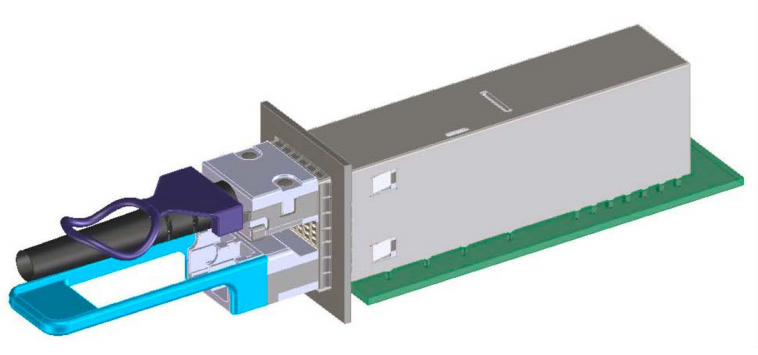
QSFP-DD, Quad Small Form-factor Pluggable Double-Density, is a new module and cage/connector system similar to current QSFP, but with an additional row of contacts providing for an eight lane electrical interface. The term “Double-Density” refers to the doubling of the number of high-speed electrical interfaces that the module supports compared to the regular QSFP28 module. The connector specification is ready for the new PAM4 electrical modulation format that supports 50Gb/s that provides another doubling of speed resulting is a 4x increased in port speed for the QSFP-DD compared to the QSFP28 module.

QSFP-DD

The Diagram of QSFP-DD Module and Host Interface

Next, we will analyze the features of QSFP-DD one by one.

Features and Benefits of QSFP-DD

QSFP-DD expands on the QSFP pluggable form factor, a widely adopted four-lane electrical interface.

QSFP-DD is with 2×1 stacked integrated cage/connector. Due to industry need, most pluggable form factors eventually see developed a two-high stacked cage-connector system in addition to a one-high cage connector system. Often the one-high system is included in the initial MSA specification and the two-high is left to independent individual suppliers. To serve better the industry, the QSFP-DD MSA Group chose to develop concurrently both the one-high and the two-high cage-connector systems.

SMT connector and 1xN cage, Cage design optimizations and module case optimizations enable thermal support of at least 12W per module. The QSFP-DD Specification defines power classes up to 14W as well as a >14W class. Due to innovative thermal management techniques used in the module and cage designs, QSFP-DD modules support power levels of at least 12W in a typical system design. The extensive knowledge and experience of system design with QSFP family form factors enables innovative systems solutions that could extend beyond that range. Thermal management features needed for the higher power consumption classes are relaxed for the lower power classes to avoid unnecessary costs.

QSFP-DD electrical interfaces employs eight lanes that operate up to 25Gb/s NRZ modulation or 50Gb/s PAM4 modulation, providing solutions up to 200Gb/s or 400Gb/s aggregate. QSFP-DD can enable up to 14.4Tb/s aggregate bandwidth in a single switch slot. By quadrupling aggregate switch bandwidth while maintaining port density, QSFP-DD can support continuing growth in network bandwidth demand and datacenter traffic.

Before the emergence of QSFP-DD, the most popular interfaces in the networking industry consisted of single (SFP/SFP+) or quad lanes (QSFP+/QSFP28). However, to accommodate expected demand for data bandwidth or channel capacity, eight lane interfaces are being defined in venues such as Ethernet. The currently available form factors that support eight lane interfaces do not have all the desired features or density necessary to support the next generation systems that plan to implement these higher rate interfaces. Thus, the QSFP-DD MSA group extended and defined QSFP-DD based on QSFP (QSFP+/QSFP28).

QSFP-DD vs. QSFP (QSFP+/QSFP28)

  1. The new QSFP-DD interface expands on the QSFP pluggable form factor, a widely adopted four-lane electrical interface used across Ethernet switches that enables interconnection between switches or to servers. QSFP’s four electrical lanes operate at 10Gb/s or 25Gb/s, providing solutions for 40Gb/s or 100Gb/s aggregate. The new QSFP-DD pluggable form factor’s electrical interfaces employ eight lanes that operate up to 25Gb/s NRZ modulation or 50Gb/s PAM4 modulation, providing solutions up to 200Gb/s or 400Gb/s aggregate. This can enable up to 14.4Tb/s aggregate bandwidth in a single switch slot and address rapid datacenter traffic growth.
  2. Systems designed with QSFP-DD modules are backwards compatible, allowing them to support existing QSFP modules and provide flexibility for end users and system designers. Backwards compatibility is critically important to the industry. Since ASICs are designed to support multiple interface rates, it is critically important that the system can take advantage of this. End users can take advantage of the newer ASIC and system products with lower port costs and are able plug in a wide range of currently available QSFP modules to support their desired media and reach without needing to have separate system products. This greatly decreases the risks associated with implementing new equipment. System designers can build common products that support a multiple of pluggable variants while leveraging known technologies and designs. Module designers do not need to port their lower rate designs into new non-backwards compatible form factors lowering their overall costs. The economy of scale achieved due to backwards compatibility make it highly desirable.
  3. The system port densities are identical between QSFP-DD and QSFP28 module specifications. However, since each QSFP-DD port can accommodate 8 lanes instead of 4, QSFP-DD doubles the number of ASIC ports it supports for existing interfaces such as CAUI-4.
  4. The mechanical interface for QSFP-DD on the host board is slightly deeper than for QSFP28 to accommodate the extra row of contacts. The height and width are identical to the QSFP form factor enabling system designers to achieve identical system port count densities for QSFP28 or QSFP-DD based designs. You can plug any current QSFP or QSFP28 module into the QSFP-DD 1×1 or the 2×1 cage/connector combinations.

In summary, QSFP-DD is a little longer than QSFP+/QSFP28 but the port density is the same, and the bandwidth is increased to 10 times or 4 times of the latter, and it is backwards compatible, which means customers can skip the QSFP system and directly deploys the QSFP-DD system, which greatly reduces the equipment costs.

At the beginning of this article, we mentioned that some optical transceiver manufacturers have also introduced 400G optical modules with OSFP and CFP8 form-factors. Let’s compare QSFP-DD and OSFP, QSFP-DD and CFP8 to see how they differ.

QSFP-DD vs. OSFP vs. CFP8

QSFP-DD vs. OSFP vs. CFP8

First, let’s take a look at OSFP first. Not long ago (January 16, 2019), OSFP MSA released version 2.0. According to its description, the OSFP is a new pluggable form factor with eight high speed electrical lanes that will initially support 400Gb/s (8x50G). It is slightly wider and deeper than the QSFP but it still supports 36 OSFP ports per 1U front panel, enabling 14.4Tb/s per 1U.

Tips: In the latest release of OSFP MSA, OSFP already supports 800Gb/s, which may be the reason why OSFP is also one of the popular 400G form-factors.

  • Size — According to the previous introduction, OSFP seems to have little difference from QSFP-DD, just “slightly wider and longer” than QSFP-DD. However, after comparing their specific size values, we found that the difference is not just a little bit. The width, length and thickness of QSFP-DD are 18.35mm, 89.4mm and 8.5mm, while those of OSFP are 22.58mm, 107.8mm and 13.0mm. If the module is roughly calculated as a cuboid, the volume of the OSFP could be more than twice that of QSFP-DD, and it is obvious that the former is much larger.
  • Thermal Capacity and Power Consumption — The QSFP-DD is smaller in size, so its thermal capacity is only 7 to 12 watts. While the OSFP is larger in size, its thermal capacity can reach 12 to 15 watts. The larger the thermal capacity, the greater the power consumption that the optical module can withstand. However, with the advancement of technology, some industry-leading manufacturers have been able to reduce the power consumption of optical modules far below the upper limit of thermal capacity specified by MSA, so the larger thermal capacity does not seem to be a real advantage in the future. Consistent with the thermal capacity, OSFP’s power consumption is generally higher than QSFP-DD. However, as we all know, the lower the power consumption, the better. As the world’s leading innovator of optical interconnect design, Gigalight always focus low power consumption as one of the primary goals of optical transceivers. For example, the Gigalight 100G QSFP28 SR4 optical transceiver has been optimized to reduce power consumption to less than 2.5 watts, which is nearly 30% lower than the 3.5 watts in the industry. The Gigalight 200G/400G optical modules also have the advantage of low power consumption in the industry.
  • Backwards Compatibility — OSFP is as backward compatible with QSFP+/QSFP28 as QSFP-DD, but requires an additional OSFP to QSFP adapter. Since the OSFP is slightly wider and deeper than the QSFP, it is possible to build an adapter that supports existing 100G QSFP optics modules (QSFP28) in a OSFP cage.
  • Bandwidth — QSFP-DD currently only supports up to 400Gb/s, but OSFP can support up to 800Gb/s. Considering scalability, OSFP is slightly better than QSFP-DD. But 800Gb/s is too early, and when 800Gb/s starts to deploy, there may be better options.

In summary, QSFP-DD is mainly used to apply 400G networks that are currently being deployed (and 200G over 100G to 400G), while OSFP is more likely to be prepared for future 800G networks. Therefore, combined with the status quo, QSFP-DD is more suitable as a form-factor of 400G optical transceivers.

QSFP-DD vs. CFP8

The CFP series started from CFP, went to CFP2, then to CFP4, and finally to CFP8, which is also a long-established form-factor series. Compared to the QSFP series, the CFP series seems to have been less popular, for obvious reasons — large size and high power consumption. The first two companies that promoted the development of CFP MSA (Finisar and Oclaro) have also been acquired, and we seem to feel the end of CFP.

Let’s take a look at CFP8. The CFP8 hardware specification was officially released by the CFP MSA on March 17, 2017, in the same period as the 2.0 version of the QSFP-DD MSA was released. Comparing the two form-factors, we seem to have foreseen the decline of CFP8.

  • Size — The size of CFP8 (41.5mm*107.5mm*9.5mm) is significantly larger than QSFP-DD, and the volume is more than three times that of QSFP-DD, even more than 30% larger than that of OSFP. Since the CFP series optical modules have been positioned for telecommunication applications, and the port density requirements are not as high as in the data center, so the size is acceptable. However, with the advancement of technology, the QSFP series optical modules are also beginning to be suitable for telecommunication applications, and the power consumption of QSFP series optical modules is much lower than that of CFP series optical modules. Therefore, the dominant position of CFP series optical modules in telecommunication applications is at stake.
  • Thermal Capacity and Power Consumption — The thermal capacity and power consumption of CFP8 is much higher than QSFP-DD. The introduction of thermal capacity and power consumption has been introduced in the previous QSFP-DD vs. OSFP, and the truth is the same.
  • Backwards Compatibility — There is not any mention of backwards compatibility in the hardware specification of CFP8 (in fact, the entire CFP series does not seem to be backwards compatible). For CFP and CFP2 series optical modules, the CFP to QSFP28 adapter and CFP2 to QSFP28 adapter have been available for a long time, indicating that some users have switched to QSFP28 optical modules.
  • Bandwidth — The maximum bandwidth of CFP8 and QSFP-DD is 400Gb/s, but CFP8 only supports 400Gb/s (16x25G or 8x50G), while QSFP-DD supports both 200Gb/s (8x25G) and 400Gb/s (8x50G).

In summary, QSFP-DD seems to be a better choice than CFP8, regardless of any aspect.

Conclusion

By analyzing the features of QSFP-DD and comparing it to other 400G optical module form-factors, we found that QSFP-DD has unparalleled advantages in 400G applications such as data center interconnects. It is expected that when the world’s leading hyperscale data centers start to deploy 400G, QSFP-DD will become the mainstream form-factor of 400G optical modules.

Originally published at Gigalight.

Source at QSFP-DD Might Be the Mainstream Form-factor of 400G Optical Transceivers.

PAM4 — The High-Speed Signal Interconnection Technology of Next-Generation Data Center

What Is PAM4?

PAM4 (4-Level Pulse Amplitude Modulation) is one of PAM modulation technologies that uses 4 different signal levels for signal transmission. Each symbol period can represent 2 bits of logic information (0, 1, 2, 3), that is, four levels per unit time.

In the data center and short-distance optical fiber transmission, the modulation scheme of NRZ is still adopted, that is, the high and low signal levels are used to represent the (1, 0) information of the digital logic signal to be transmitted, and one bit of logical information can be transmitted per signal symbol period.

However, as the transmission rate evolves from 28Gb/s to a higher rate, the electrical signal transmission on the backplane will cause more severe loss to the high-frequency signal, and higher-order modulation can transmit more data in the same signal bandwidth. Therefore, the industry is increasingly calling for higher-order PAM4 modulation. The PAM4 signal uses four different signal levels for signal transmission, and each symbol period can represent 2 bits of logical information (0, 1, 2, 3). Since the PAM4 signal can transmit 2 bits of information per symbol period, to achieve the same signal transmission capability, the symbol rate of the PAM4 signal only needs to reach half of the NRZ signal, so the loss caused by the transmission channel is greatly reduced. With the development of future technologies, the possibility of using more levels of PAM8 or even PAM16 signals for information transmission is not ruled out.

NRZ vs. PAM4: The comparison of waveforms and eye diagrams between NRZ and PAM4 signals

And then, if the optical signal can also be transmitted by using the PAM4, the clock recovery and pre-emphasized PAM4 signal can be directly realized when the electro-optical transmitting is performed inside the optical module, therefore, the unnecessary step of converting the PAM4 signal into the NRZ signal of 2 times the baud rate and then performing related processing is eliminated, thereby saving the chip design cost.

Why PAM4?

The end-to-end transmission system includes fiber optic and fiber-optic transmission systems. Since the fiber transmission can easily reach the rate of 25Gbd so that the research progress of transmitting PAM4 on the fiber has been progressing slowly. For fiber-optic transmission systems, from NRZ moving to PAM4 is considered in terms of cost. If you do not need to consider the cost, there are other related modulation technologies can be used in the long-distance range, such as DP-QPSK, which can transmit the baud rate signal above 50Gbd for several thousand kilometers. However, in the data center field, the transmission distance is generally only 10km or less. If the optical transceiver using PAM4 technology is adopted, the cost can be greatly reduced.

For 400GE, the largest cost is expected to be optical components and related RF packages. PAM4 technology uses four different signal levels for signal transmission. It can transmit 2 bits of logic information per clock cycle and double the transmission bandwidth, thus effectively reducing transmission costs. For example, 50GE is based on a single 25G optical device, and the bandwidth is doubled through the electrical layer PAM4 technology, which effectively solves the problem of high cost while satisfying the bandwidth improvement. The 200GE/400GE adopts 4/8 channel 25G devices, and the bandwidth can be doubled by PAM4 technology.

For data center applications, reducing the application of the device can significantly reduce costs. The initial goal of adopting higher order modulation formats is to place more complex parts on the circuit side to reduce the optical performance requirements. The use of high-order modulation formats is an effective way to reduce the number of optics used, reduce the performance requirements of optics, and achieve a balance between performance, cost, power, and density in different applications.

In some application scenarios, high-order modulation formats have been used for several years on the line side. However, since the client side needs are different from the line side, so other considerations are needed.

For example, on the client side, the main consideration is the test cost, power consumption and density. On the line side, spectrum efficiency and performance are mainly considered, and cost reduction is not the most important consideration. By using linear components on the client side and the PAM4 modulation format that is directly detected, companies can greatly reduce test complexity and thus reduce costs. Among all high-order modulation formats, the lowest cost implementation is PAM4 modulation with a spectral efficiency of 2 bits/s/Hz.

PAM4

Conclusion

As a popular signal transmission technology for high-speed signal interconnection in next-generation data centers, PAM4 signals are widely used for electrical and optical signal transmission on 200G/400G interfaces. Gigalight has a first-class R&D team in the industry and has overcome the signal integrity design challenges of PAM4 modulation. Gigalight’s 200G/400G PAM4 products include 200G QSFP56 SR4, 200G QSFP56 AOC, 200G QSFP56 FR4, 400G QSFP56-DD SR8, 400G QSFP56-DD AOC, etc.

All of the PAM4 products from Gigalight can be divided into digital PAM4 products and analog PAM4 products. The digital PAM4 products adopt DSP solutions which can support a variety of complex and efficient modulation schemes. The electric port has strong adaptability and good photoelectric performance. And the analog PAM4 products simulate CDR with low power consumption and low cost. Gigalight always adheres to the concept of innovation, innovative technology, and overcomes difficulties. It invests a lot of human resources and material resources in the research and development of next-generation data center products.

Originally published at dci.ti-da.net

La tecnologia coerente si sposta sul mercato a lungo raggio nel data center

Con l’aumentare della distanza di trasmissione e della capacità dei dati, la perdita nel processo di trasmissione ottica aumenta. L’interconnessione del data center deve superare il problema della trasmissione di informazioni a lungo raggio, quindi la tecnologia coerente diventa piuttosto importante nell’interconnessione del data center.

Trasmissione coerente

La tecnologia coerente si sposta sul mercato a lungo raggio nel data center

I due fasci di ottica coerente interferiranno nell’area in cui si incontrano.

La tecnologia coerente si sposta sul mercato a lungo raggio nel data center

La modulazione coerente e le tecniche di rilevamento eterodina sono utilizzate principalmente in comunicazioni ottiche coerenti.

La modulazione coerente consiste nell’utilizzare il segnale da trasmettere per modificare la frequenza, la fase e l’ampiezza della portante ottica (mentre la rilevazione dell’intensità cambia solo l’intensità dell’ottica), che richiede che il segnale ottico abbia una certa frequenza e fase (mentre l’ottica naturale non ha una determinata frequenza e fase), dovrebbe essere un’ottica coerente. Un laser è una specie di ottica coerente.

La rivelazione dell’eterodina utilizza un laser generato da un oscillatore locale per miscelare con l’ottica del segnale di ingresso in un mixer ottico per ottenere un segnale di frequenza intermedio che cambia in base alla stessa frequenza, fase e ampiezza dell’ottica del segnale.

La tecnologia di ricezione coerente digitale consente al sistema di trasmissione ottica di avere tolleranza di dispersione e tolleranza della modalità di polarizzazione sufficienti senza considerare gli effetti della dispersione cromatica e della dispersione della modalità di polarizzazione sulla trasmissione, il che apporta una serie di vantaggi alla costruzione, all’esercizio e alla manutenzione della rete.

La tecnologia di ricezione digitale coerente offre una serie di vantaggi

  • Semplifica la compensazione della dispersione ottica e il progetto di multiplazione di polarizzazione sulla linea di trasmissione, e la progettazione del circuito è più semplice.
  • Elimina la dipendenza dalla bassa fibra PMD ed è adatto per la fibra di trasmissione di varie specifiche, che è conveniente per l’aggiornamento della velocità della linea in fibra.
  • Elimina l’influenza dell’effetto non lineare della fibra DCF della linea di trasmissione, riduce il numero di amplificatori di linea e l’influenza del rumore ASE, riduce il costo della linea e migliora la capacità nella trasmissione a lungo raggio del sistema.
  • Il tempo di recupero della protezione è inferiore a 50 ms (diverso dal sistema 40G). L’algoritmo di compensazione della dispersione adattativa di elaborazione del segnale digitale 100G converge rapidamente e soddisfa pienamente i requisiti di ritardo di recupero della classe carrier.
  • Il ritardo di trasmissione della linea è ridotto. Secondo il calcolo del ritardo della fibra di 1 km 5us, la riduzione del ritardo causata dall’eliminazione della fibra DCF è molto considerevole, il che è significativo per l’ambiente applicativo sensibile al ritardo.

La tecnologia di trasmissione coerente può essere utilizzata nelle applicazioni 100G e 400G perché consente ai service provider di inviare più dati su fibra esistente, riducendo il costo e la complessità degli aggiornamenti di rete per l’espansione della larghezza di banda. Le attuali soluzioni di temporizzazione per l’ottica coerente non sono state ottimizzate in termini di costi e dimensioni, richiedendo un mix diversificato di VCSO, generatori di clock e dispositivi discreti.

La tecnologia coerente può anche ottenere il più basso costo totale di proprietà a 100G e oltre 100G, eliminando il tradizionale costoso modulo di compensazione della dispersione DCM e compensando digitalmente la perdita di rumore della fibra utilizzando un chip DSP basato su CMOS. La tecnologia coerente consente una regolazione flessibile della lunghezza della fibra, garantendo al tempo stesso la possibilità di estendere la portata dei dati a 400 G per lunghezza d’onda, con una maggiore capacità di ridurre il costo per bit.

Come funziona la tecnologia di trasmissione coerente 100G?

Nella soluzione coerente 100G, un laser (stessa frequenza) della stessa lunghezza d’onda centrale del laser trasmittente viene utilizzato all’estremità ricevente. Quindi, attraverso l’elaborazione del circuito di sincronizzazione, la fase dell’estremità ricevente viene mantenuta uguale all’estremità trasmittente (in fase), formando così una condizione coerente.

Dopo aver generato le condizioni coerenti, è conveniente ripristinare il segnale “modulato in fase”. Con una ricezione coerente, le prestazioni saranno migliori.

La ricezione coerente non può solo migliorare il rapporto segnale / rumore del segnale ricevuto, ma anche compensare la perdita causata da alcuni segnali durante la trasmissione. La ricezione coerente può preservare l’informazione di fase del segnale ottico, in modo che i due stati di polarizzazione possano essere ripristinati mediante elaborazione elettrica e compensare alcuni danni causati dalla trasmissione a lungo raggio. La trasmissione coerente basata su tanti vantaggi è la prima scelta nella trasmissione a lungo raggio nel data center.

Gigalight ha sviluppato in modo indipendente un ricetrasmettitore ottico coerente da 100G CFP-DCO . Ha personalizzato la ricerca e sviluppo per le applicazioni di reti metropolitane per l’interconnessione di data center, incarnando pienamente le caratteristiche di usabilità, flessibilità, basso consumo energetico e bassa latenza, rappresentando la direzione futura dello sviluppo di dispositivi di comunicazione ottica ad alta velocità.

Originariamente pubblicato su Gigalight’s Medium Blog

Which Is Better? PAM4 or Coherent Technology for 80km Links

A significant portion of Data Center Interconnections (DCIs) and telecom router-to-router interconnections rely on simple ZR or 80km transceivers. The former is mostly based on 100Gbps per 100GHz ITU-T window C-band DWDM transceivers, while the latter is mostly 10G or 100G grey wavelength transceivers. In DWDM links, the laser wavelength is fixed to a specified grid, so that with DWDM Mux and Demux 80 or more wavelength channels can be transported through a single fiber. Grey wavelengths are not fixed to a grid and can be anywhere in the C-Band, limiting capacity to one channel per fiber. DCI links tend to use DWDM because they have to utilize the optical fiber bandwidth as much as possible due to the extremely high-volume traffic between data centers.

Another emerging 80km market is the Multi-System Operator (MSO) or the CATV optical access networks. This need emerges because MSOs are running out of their access optical fibers and they need a transmission technology which would allow them to grow to a very large capacity by using the remaining fibers. For this reason they need to use DWDM wavelengths to pack more channels in a single fiber.

The majority of the 10G transceivers on 80km links will be replaced by 100G or 400G transceivers in the coming years. For that to happen, there are two modulation techniques to enable 80km 100G transceivers.

  • 50G PAM4 with two wavelengths in a 100G transceiver
  • Coherent 100G dual-polarization Quadrature Phase Shifted Keying (DP-QPSK)

Generally speaking, PAM4 is a low-cost solution but require active optical dispersion compensation (which could be a big headache as well as extra expense to data center operators) and extra optical amplification to compensate for the dispersion compensators. By contrast, Coherent approaches do not need any dispersion compensation and the price is coming down rapidly, especially when the same hardware can be configured to upgrade the transmission data rate per wavelength from 100G to 200G (by using DP-16QAM modulation).

When 400G per wavelength is needed in a DCI network within a 100GHz ITU-T window, coherent technology is the only cost-effective solution, because it will not be feasible for PAM4 to achieve the same high spectral efficiency of 4 bit/sec/Hz.

On the standards front, many standards organizations are adopting coherent technology for 80km transmission. The Optical Inter-networking Forum (OIF) will adopt coherent DP-16QAM modulation at up to 60Gbaud (400G per wavelength) in an implementation agreement on 400G ZR. This is initially for DCI applications with a transmission distance of more than 80km, and vendors may come up with various derivatives for longer transmission distances. Separately, CableLabs has published a specification document for 100G DP-QPSK coherent transmission over a distance of 80km aimed at MSO applications. In addition, IEEE802.3ct is in the process of adopting coherent technologies for 100G and 400G per wavelength transmissions over 80km.

As data rates increase from 100G to 400G and capacity requirements per fiber are driven by DCI needs, and assisted by volume driven cost reductions in coherent optics and in coherent DSPs, we expect coherent transmission to be the technology of choice for 80km links.